Time to catch up on the additions and improvements on the weather station since I built the first MVP.
Hardware
Overview
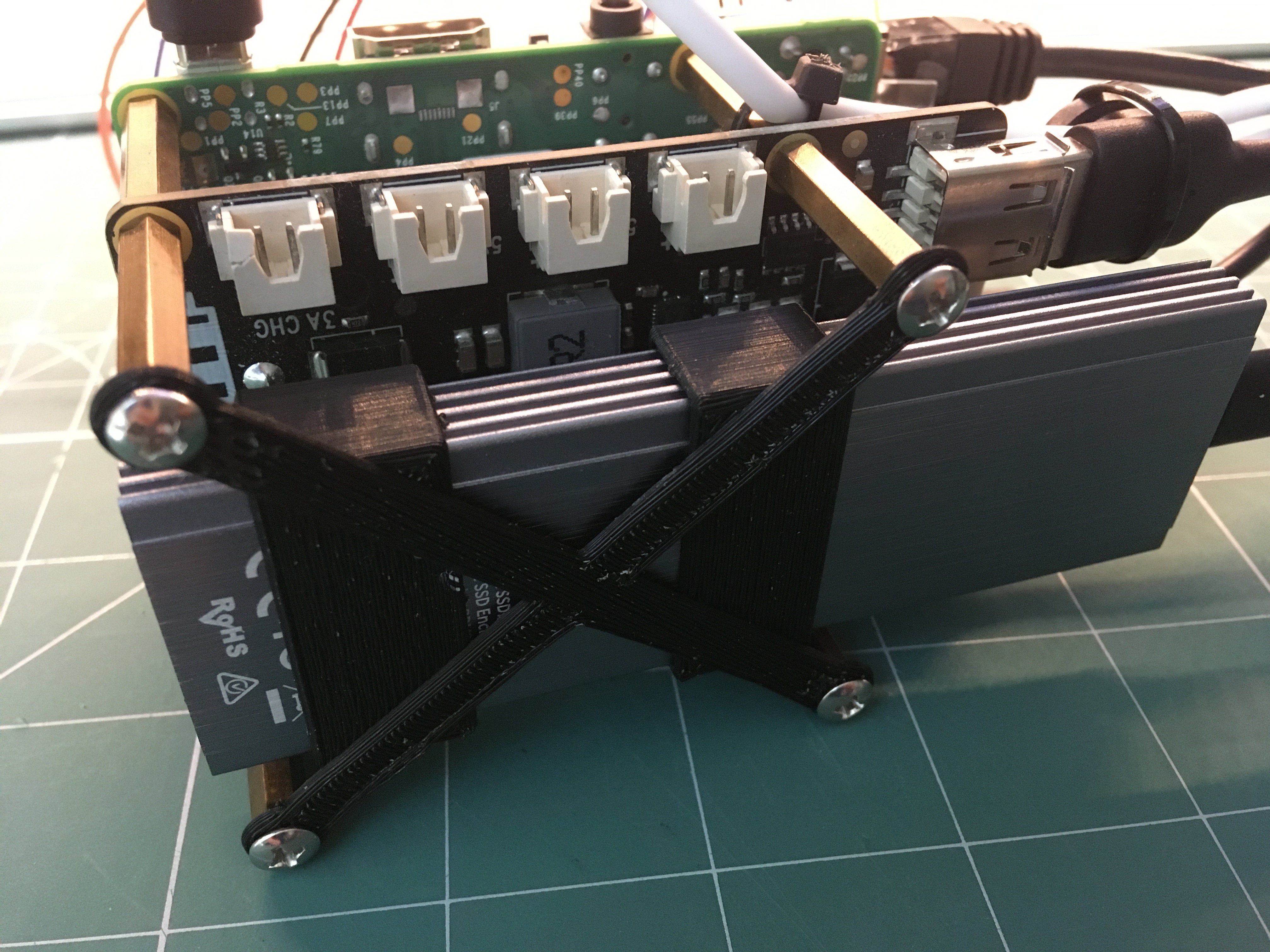
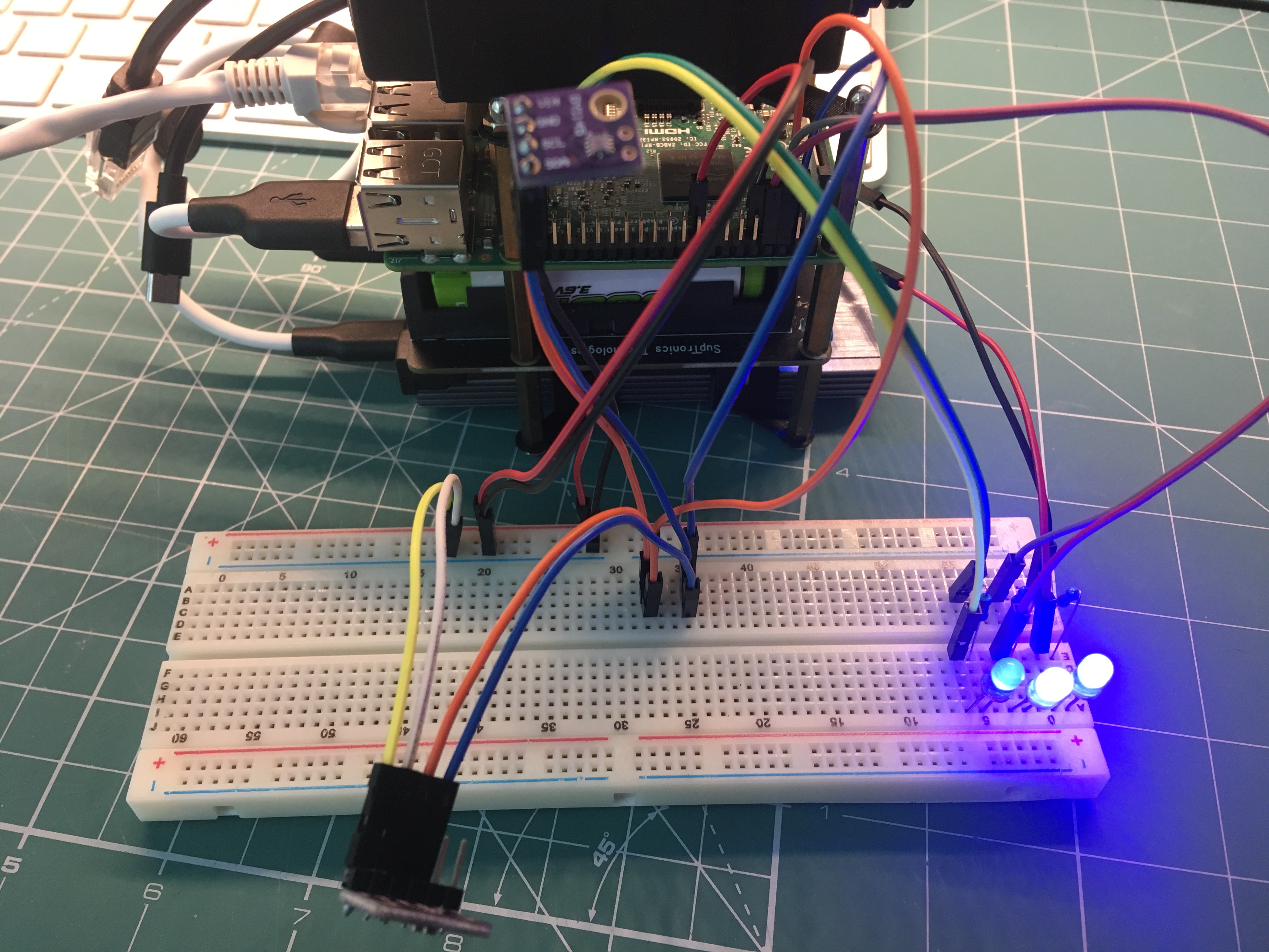
So here’s what the weather station looks like currently:
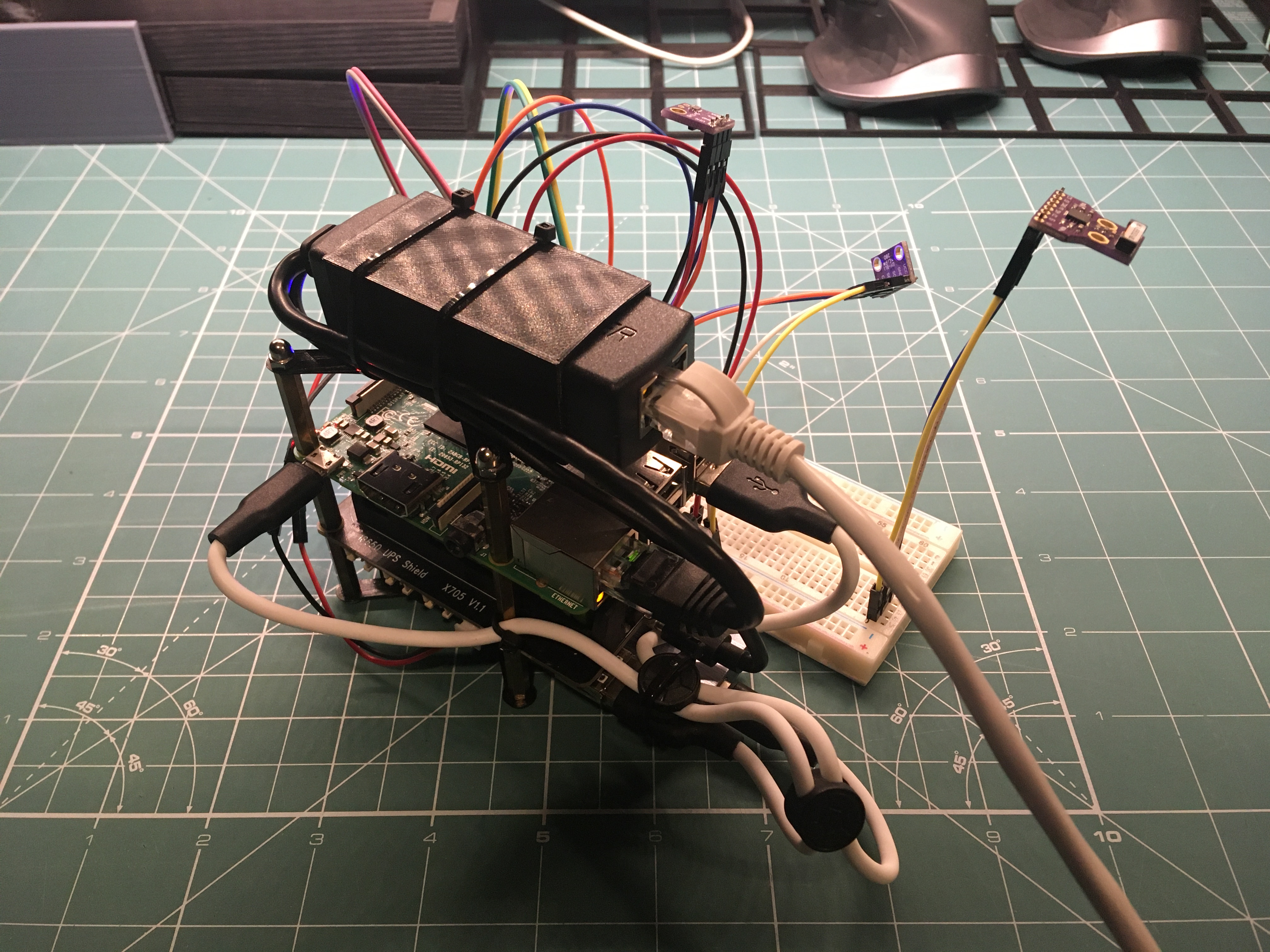
The new things are:
- PoE+ adapter and 3D-printed mounting bracket
- Replacement SSD enclosure and 3D-printed mounting bracket
- LED indicators for UPS board power, Pi power status and SSD activity
- SI1145 light sensor
The AS3935 sensor plugged in at the right isn’t connected yet - that’s just so I don’t misplace it.
PoE+ Adapter
I have a few these PoE+ adapters in my parts cabinet so I just threw one on to see what would happen with power being supplied by my UniFi 24 port switch. It worked, but after about 5 days the system lost power.
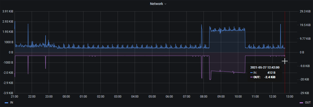
After fully recharging the batteries via the barrel jack I hooked up my Ruideng USB in-line multimeter to determine that when the UPS board is already fully charged it draws about 1 milliamp from the PoE+ adapter:
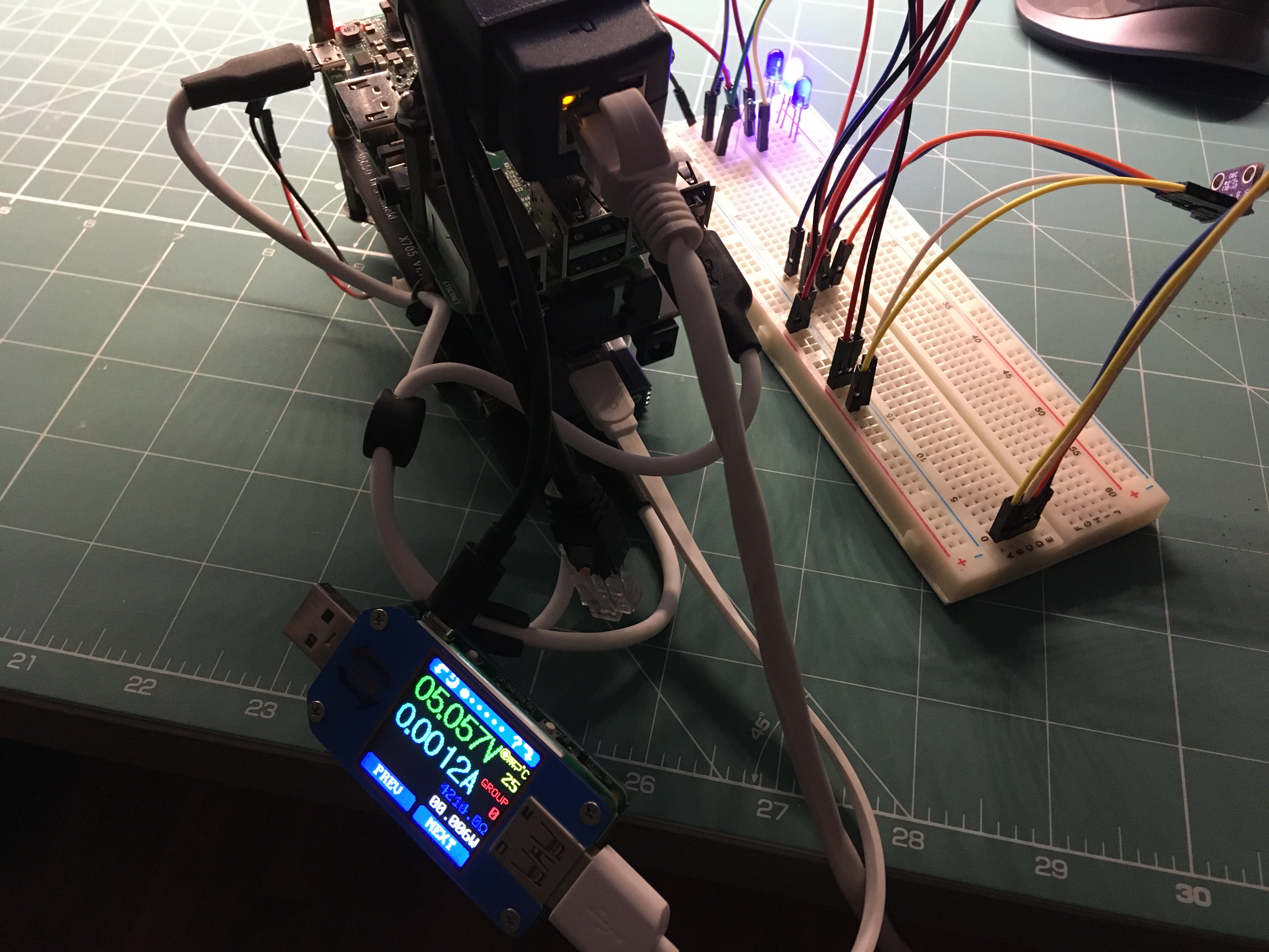
Even though the Pi is running and drawing around half an amp:
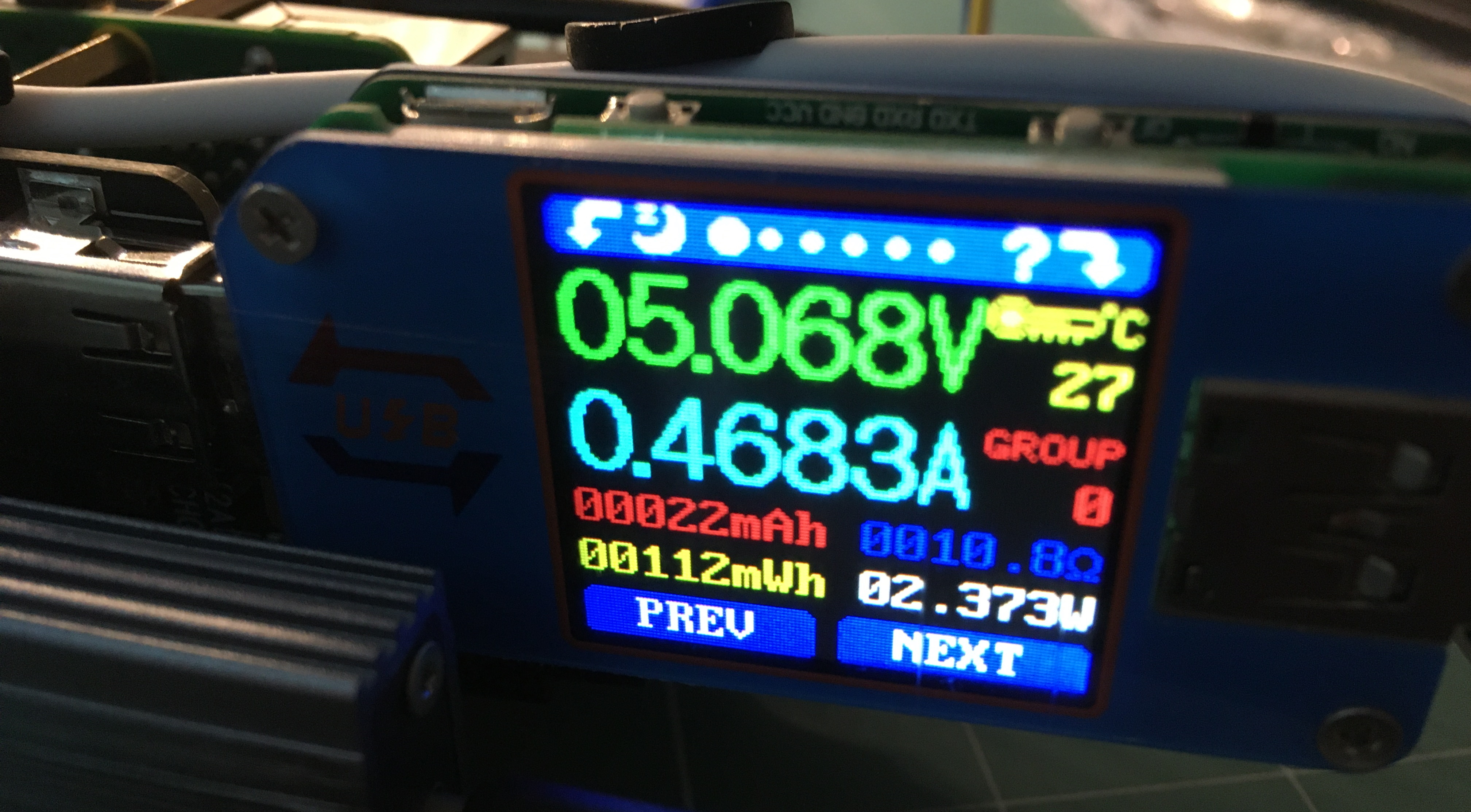
In other words the UPS is driving the board off batteries even when connected to power. Eventually it hits a threshold and starts charging again, but apparently not effectively enough because eventually the batteries run flat and the system dies. In short - this is not a UPS, it’s a powerbank.
I have ordered a 52pi UPS board. I believe it’s a better unit - but it’s really hard to tell from the data sheet so has to be tested. This board has a built-in RTC (a nice-to-have for my application) and a power meter so you can read draw and battery level via I2C which will be cool if I can get that to work. Ideally I will read those values and export them to Prometheus.
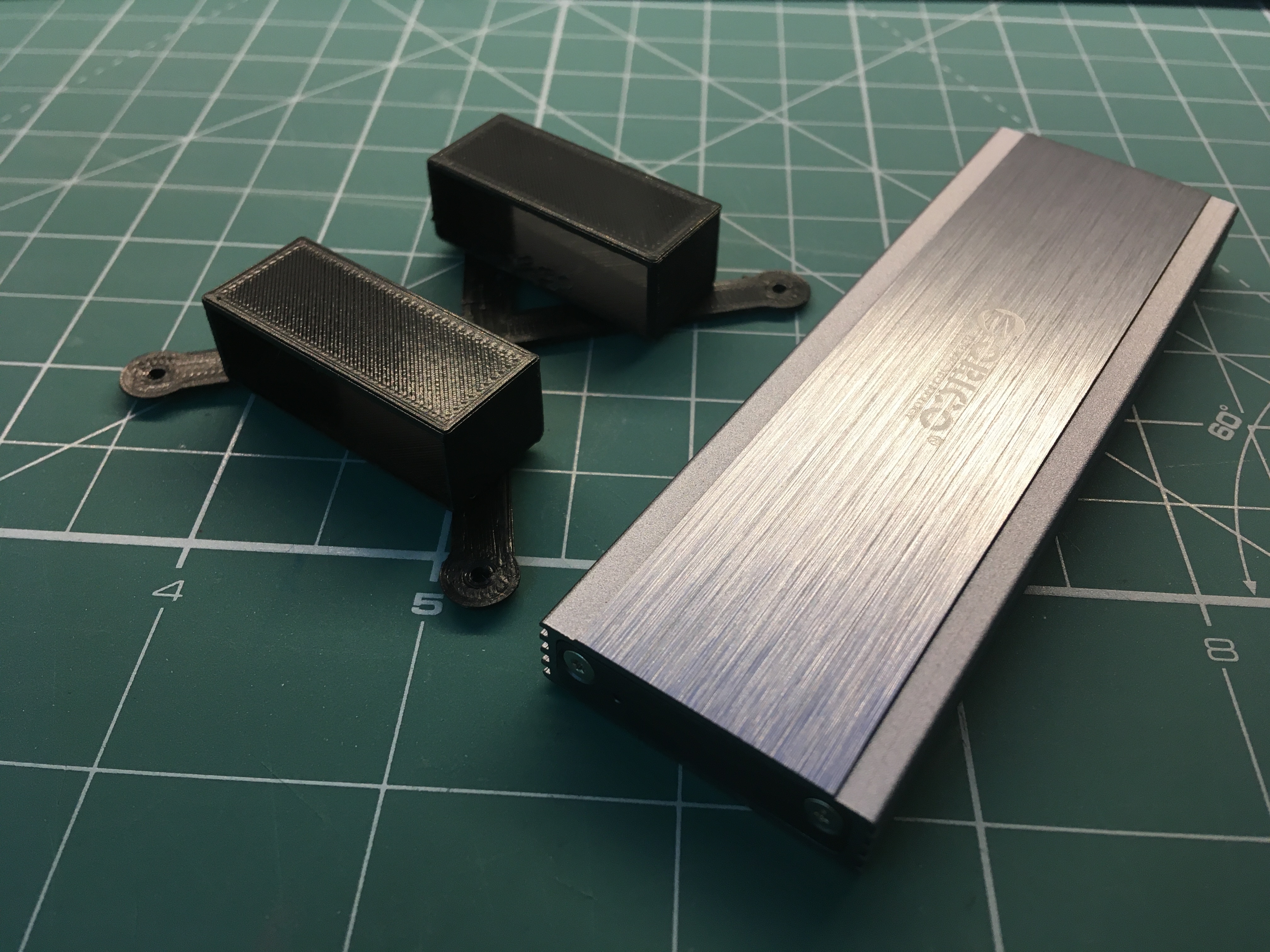
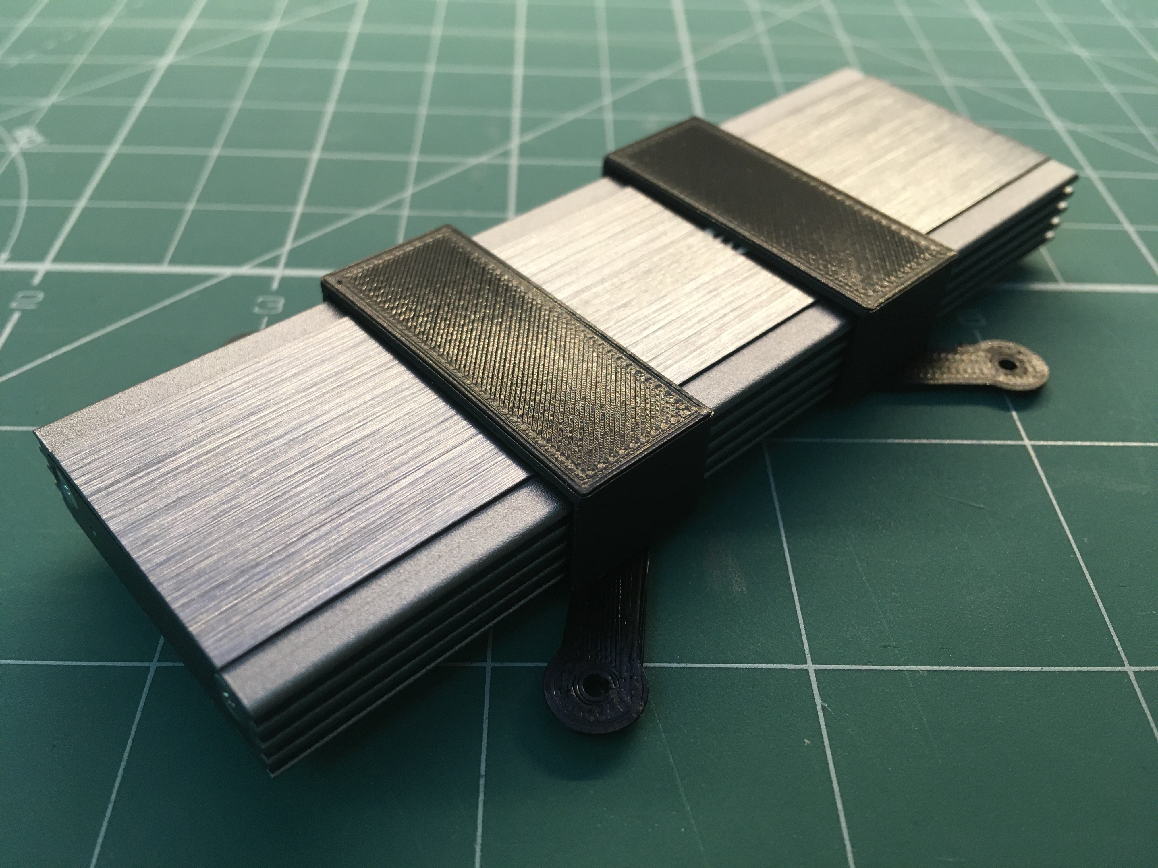
Replacement SSD Enclosure
On Tuesday morning last week I woke up to a dead weather station. From the Prometheus-exported host telemetry I could see that it went offline around 2:20am local time.
Through a process of elimination I determined that it was the interface board in the SSD enclosure that had failed and that the SSD itself was fine so I ordered in a new Orico brand enclosure. This one was a different size to the original so I had to print a new bracket for it:
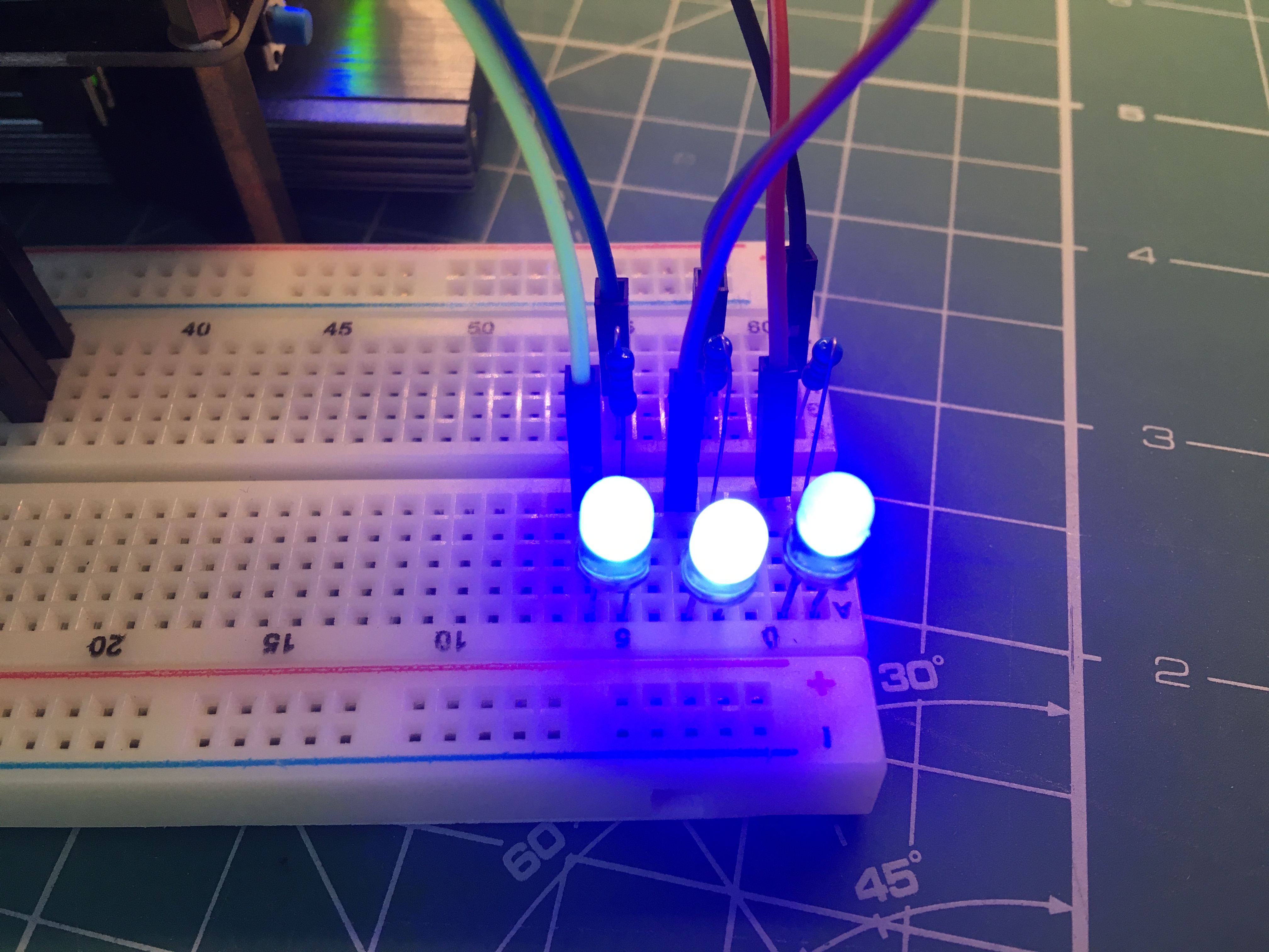
LED Indicators
Eventually this thing is going to be mounted in a cabinet on a pole in a field, so it would be helpful if the power and HDD lights were easy to see. Fortunately Raspberry Pi supports breaking out LED’s so it was a 5 minute job to add external power and HDD activity LED’s. I also connected a LED to one of the JST outputs on the UPS board to indicate when the board is supplying power:
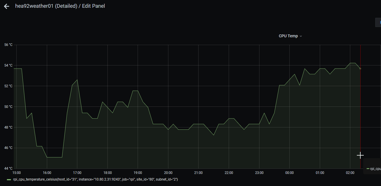
Endurance Test
Even though the current UPS board is no good, I ran an endurance test to see how long these two 18650 cells could run the host for and the result was just under 16 hours.
Once I get the replacement UPS board I will re-run the endurance test, but this is already a very good indicative result - being able to survive a power outage of more than half-a-day will make this a very robust system.
Sensors
I added one new sensor in this iteration. Originally I was going to add the I2C lightning sensor which was already in my parts bin but during the week last week the GY/SI1145 light sensor came in so I hooked that up instead.
I broke out the I2C bus to a breadboard and reconnected the BME280 plus added the SI1145 - blue is data and orange is clock:
Verified connectivity and found the SI1145 at 0x60 while the BME280 is still at 0x76:
pi@hea92weather01:~ $ i2cdetect -y 1
     0  1  2  3  4  5  6  7  8  9  a  b  c  d  e  f
00:          -- -- -- -- -- -- -- -- -- -- -- -- --
10: -- -- -- -- -- -- -- -- -- -- -- -- -- -- -- --
20: -- -- -- -- -- -- -- -- -- -- -- -- -- -- -- --
30: -- -- -- -- -- -- -- -- -- -- -- -- -- -- -- --
40: -- -- -- -- -- -- -- -- -- -- -- -- -- -- -- --
50: -- -- -- -- -- -- -- -- -- -- -- -- -- -- -- --
60: 60 -- -- -- -- -- -- -- -- -- -- -- -- -- -- --
70: -- -- -- -- -- -- 76 --
Then added the code to read the SI1145 and include it in the Influx line protocol message published to MQTT:
import SI1145.SI1145 as SI1145

...

#
# GY1145 / SI1145
#

si1145 = SI1145.SI1145()

...

# SI1145
lightVisible = si1145.readVisible()
lightUV = si1145.readUV()
lightIR = si1145.readIR()

# Publish
influx = "weather,station=" + weather_station_id + " " + \
	"humidity=" + str(humidity) + \
	",pressure=" + str(pressure) + \
	",temperature=" + str(temperature) + \
	",visible=" + str(lightVisible) + \
	",uv=" + str(lightUV) + \
	",ir=" + str(lightIR)
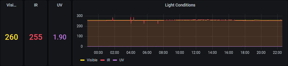
And added some panels to my weather station dashboard in my main Grafana instances:
Data Plane
Overview
Most of my time on this iteration was spent on the data plane. The improvements here were:
- Handle SIGTERM
- MQTT Auto-Reconnect
- Containerized the sensor-reader Python script
- Added a custom bridge network to connect the three Docker Compose stacks
- Added an on-prem MQTT broker and InfluxDB storage
- Configured the edge MQTT broker to bridge to the on-prem MQTT broker
- Connect Grafana to use the on-prem InfluxDB instead of edge InfluxDB
- Connected my Home Assistant instance to MQTT and added visualizations
- De-hardcode sensor-reader
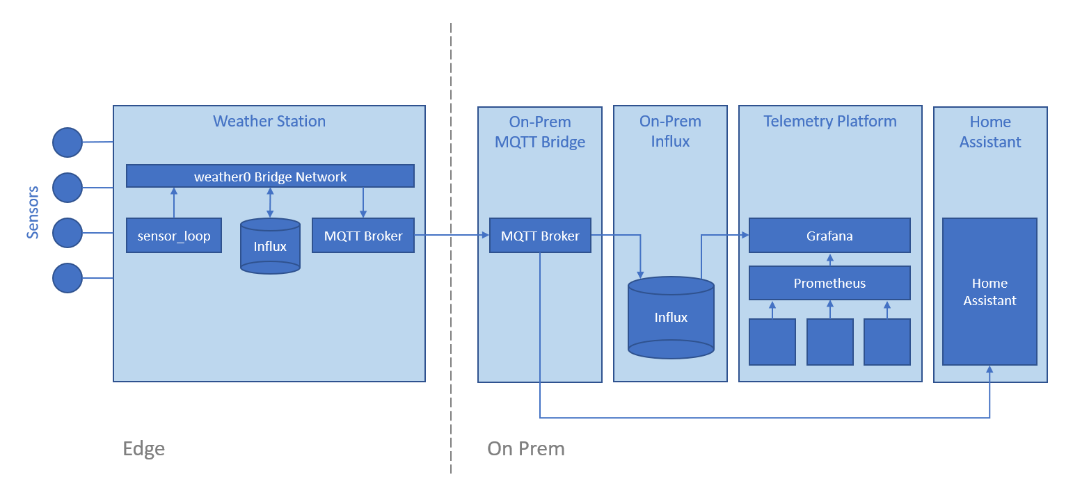
The data plane now looks like this:
Handle SIGTERM
In order to be a good container citizen I added support for SIGTERM and SIGINT Linux signals - this is the skeleton for signal handling:
class SensorReader:

	def __init__(self):
		self.stopped = False

	def run():
		while not self.stopped:
            # Process sensors
            sleep(1)

	def stop(self, signal, frame):
		print("Stopping SensorReader")
		self.stopped = True

def main():
	sensorReader = SensorReader()
	signal.signal(signal.SIGINT, sensorReader.stop)
	signal.signal(signal.SIGTERM, sensorReader.stop)
	sensorReader.run()

if __name__ == "__main__":
	main()
This was adapted from a post but I’ve misplaced the reference.
MQTT Auto-Reconnect
My original MQTT implementation was bare bones. I’ve added code based on some helpful articles from Steves Internet Guide to track connection state and leverage Paho MQTT’s built-in auto-reconnect functionality:
		#
		# Configure MQTT CLient
		#

		def mqtt_on_connect(client, userdata, flags, rc):
			if rc == 0:
				print("Connected to MQTT broker")
				client.connected_flag = True
			else:
				print("Failed to connect")

		def mqtt_on_disconnect(client, userdata, rc):
			print("Disconnecting reason " + str(rc))
			client.connected_flag = False
			client.disconnect_flag = True

		client = mqtt.Client(weather_station_id)
		client.on_connect = mqtt_on_connect
		client.on_disconnect = mqtt_on_disconnect
		client.connected_flag = False
		client.username_pw_set(broker_username, broker_password)
		client.connect(broker_host_name, broker_port)
		client.loop_start()

		while not self.stopped and not client.connected_flag:
			print("Waiting for connection")
			sleep(1)

         while not self.stopped:

			if (client.connected_flag):

				# Read sensors and publish to MQTT

				sleep(15)

			else:
				print("Connection lost.  Waiting for reconnection")
				sleep(5)

		client.loop_stop()
		client.disconnect()
This now means if the local MQTT broker goes down, sensor-reader will retry until it can connect again and the sensor readings will flow once again.
Containerize sensor-reader
The daemon that reads sensors and publishes the values to MQTT is called sensor-reader and it’s implemented as a simple Python3 script. To Dockerize this I just had to create a requirements.txt to enumerate the packages that I had previously installed manually:
RPi.bme280
paho-mqtt
SI1145
Then created a simple Dockerfile based on the official Python image:
FROM python:3.9.5-buster

RUN mkdir /app
WORKDIR /app

COPY main.py ./
COPY requirements.txt ./
RUN pip install --no-cache-dir -r requirements.txt

CMD [ "python3", "./main.py" ]
I initially wanted to use the alpine-based image but there is a problem running it on 32-bit RPi OS without privileged mode, so I fell back to the Debian Buster based image instead.
On first run I got this error:
pi@hea92weather01:~/als_sys_host_031_hea92weather01/sensor-reader $ ./run.sh
Traceback (most recent call last):
  File "/app/./main.py", line 92, in <module>
    main()
...
FileNotFoundError: [Errno 2] No such file or directory: '/dev/i2c-1'
Which was solved by mapping that device through when running the container:
sudo docker run \
    -it --rm \
    --device /dev/i2c-1 \
    sensor-reader:latest
After successfully testing the image I created a docker-compose config for easier startup:
version: "3"
services:

  #
  # SensorReader
  #

  sensorreader:
    image: "aleisium/sensor-reader:latest"
    restart: "always"
    devices:
      - "/dev/i2c-1:/dev/i2c-1"
Custom Bridge Network
I intentionally have three separate docker-compose stacks - the reason for this is that I want to be able to easily start and stop the MQTT broker, the local InfluxDB storage and the sensor-reader independently. This could also be achieved by having a single stack with convenience scripts to selectively stop and remove containers, and I may yet do that, but for now it’s nicer having separate stacks.
The problem with separate stacks is if you make them communicate via the physical eth0 interface, connectivity is lost when the network cable is pulled.
To solve this I created a custom bridge network in Docker and connected the three stacks to it.
The bridge is created with the script network/up.sh:
#!/bin/bash

sudo docker network create --driver=bridge --subnet=10.12.1.0/16 weather0
Then each of the three stacks are connected to that network - for example, sensor-reader:
version: "3"
services:

  #
  # SensorReader
  #

  sensorreader:
    image: "aleisium/sensor-reader:latest"
    networks:
      - "weather0"
    restart: "always"
    devices:
      - "/dev/i2c-1:/dev/i2c-1"

networks:
  weather0:
    external: true
    name: "weather0"
On-Prem MQTT Broker
I established a new “central” MQTT broker on a VM under ProxMox. I also now have an InfluxDB 1.8 instance with a Telegraf agent that reads from that central MQTT and stores measurements on-prem.
The central MQTT, Influx and Telegraf configs are separate from my weather station GitHub but I’ll be adding a similar config soon to make it easier for others to re-use.
Edge MQTT Bridge to On-Prem MQTT
I’m using the venerable Mosquitto MQTT broker which supports bridging - meaning an instance of the broker can be instructed to act as a client to another broker to read and / or write messages.
I added the following bridge config to broker/config/mosquitto.conf for the MQTT broker on the weather station:
connection central
address 10.80.2.60:1883
remote_username hea92weather01
remote_password password
topic # out
This causes the weather station to forward all messages it receives to the broker at 10.80.2.60 using the specified credentials. In this syntax # is not a comment marker but a wildcard indicating “all” messages.
References:
Point Grafana to On-Prem InfluxDB
As I use Grafana Provisioning for infrastructure-as-code of my telemetry stack, I just had to commit the address change to the data source definition in Git:
apiVersion: 1

# list of datasources that should be deleted from the database
deleteDatasources:
  - name: "hea92weather01"
    orgId: 1

# list of datasources to insert/update depending
# what's available in the database
datasources:
  - name: "hea92weather01"
    type: "influxdb"
    access: "proxy"
    database: "weather"
    user: "grafana"
    password: "password"
    url: "http://10.80.2.60:8086"
Then re-launch the telemetry stack.
Home Assistant Integration
Defined a connection to the central MQTT broker in Home Assistant’s configuration.yaml:
mqtt:
  broker: "10.80.2.60"
  port: 1883
  client_id: "bkk80ha"
  username: "bkk80ha"
  password: "password"
Added sensors to subscribe to values of interest from MQTT:
  - platform: "mqtt"
    name: "HEA92 Temperature"
    state_topic: "weather/hea92weather01/temperature"
    device_class: "temperature"
    unit_of_measurement: "°C"
    value_template: "0"
  - platform: "mqtt"
    name: "HEA92 Humidity"
    state_topic: "weather/hea92weather01/humidity"
    device_class: "humidity"
    unit_of_measurement: "%"
    value_template: "0"
  - platform: "mqtt"
    name: "HEA92 Pressure"
    state_topic: "weather/hea92weather01/pressure"
    device_class: "pressure"
    unit_of_measurement: "mbar"
    value_template: "0"
  - platform: "mqtt"
    name: "HEA92 Visible Light"
    state_topic: "weather/hea92weather01/visible"
    device_class: "illuminance"
  - platform: "mqtt"
    name: "HEA92 UV"
    state_topic: "weather/hea92weather01/uv"
    device_class: "illuminance"
  - platform: "mqtt"
    name: "HEA92 IR"
    state_topic: "weather/hea92weather01/ir"
    device_class: "illuminance"
Finally added some cards to a dashboard in Home Assistant:
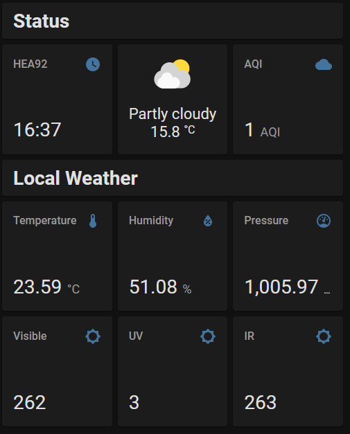
Further elaboration is available in the README.md.
References:
De-hardcode sensor-reader
Finally as a move towards making my weather station stack easily re-usable by others, I started parameterizing some of the hardcoded values in sensor-reader and moving them to environment variables so that they can be passed through the docker-compose file:
  sensorreader:
    environment:
      - "WEATHER_STATION_ID=hea92weather01"
      - "BROKER_USERNAME=hea92weather01"
      - "BROKER_PASSWORD=password"
      - "SAMPLE_INTERVAL=15"
    image: "aleisium/sensor-reader:latest"
    networks:
      - "weather0"
    restart: "always"
    devices:
      - "/dev/i2c-1:/dev/i2c-1"
Next Steps
The next improvements are:
- Processing of light readings into meaningful values
- Improve documentation and scripts to make it easier for others to re-use my configuration
- More sensors
- Test the new UPS board when it arrives
- Enclosure for the electronics
- Trial field deployment (on our condo balcony)